Lei feng's network (search for "Lei feng's network" public attention) by writer YY Shuo, from Xinjiang engineers. This article is divided into two articles, article link under here. Hello Kitty Galaxy Note 4 Case
2014 in June, I know "civilian UAV sales and prospect of what? -YY Shuo replied: "the question publish an article popular science multi-rotor aircraft technical answer, has obtained 889 in the know agree, close to 100,000 views and were forwarded by dozens of media outlets and the general public. 2014 multi-rotor aircraft market in the years before the outbreak of air, many friends tell me that it is precisely this attracts them into a number of rotary-wing aircraft industry.
Two years ago, Xinjiang Elf series updated for two generations, and updated flight control technology for two generations, and smart navigation technology from scratch, many new software and hardware products released. We also have many friends, hot market now rotary wing aircraft, many products, prices vary. In order to understand the difference between these vehicles, we must first understand the sensor technology for use on aircraft. I think now it is necessary to send a popular science article, defining "smart navigation" concept, by the way the lines about two years of Xinjiang's efforts in sensor technology.
1. the status of the aircraft
Aircraft, rotary-wing aircraft, and many manned-unmanned aircraft to stable flight, first in space, the most fundamental issue was to determine its own position and the associated State. Measurement of these States, you need a variety of sensors.
The world is three dimensional and three dimensional location of aircraft is very important. When airliner flying, are using three-dimensional position of GPS own longitude, latitude and altitude. GPS can also use the Doppler effect to measure their velocity. Later after the GPS civilian, the GPS receiver can cost more than 10 bucks for small devices, such as cars, mobile phones also received the three dimensional and three dimensional positions. Hello Kitty N4 case
For multi-rotor aircraft, only know three dimensional position and velocity are not enough because many rotary-wing aircraft in the sky when you fly, is adjusting his "attitude" to generate a direction of thrust. Fly is in fact to the side to side tilt, for example, according to some principle of physics, part of vehicle lift will push aircraft moves to the side. In order to be able to adjust your attitude, you must have some way of measuring their own attitude. Attitude is represented by three points, is three dimensional. And three-dimensional position, corresponding to the three dimensions of physical quantity is three-dimensional velocity three-dimensional, three dimensional acceleration and angular velocity, there are 15 need to measure State.
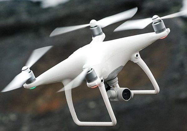
15 States are more stable rotary wing aircraft flight is a crucial role. Took "hover" this pieces looks is more spin wing aircraft most basic of capacity for, actually aircraft of controller in behind do has series "series level control": in know himself three dimensional location of based Shang, control himself of location always lock in hover location, here of control volume is a target of hover speed, dang aircraft of location is equal to hover location Shi, this target hover speed for 0, dang aircraft of location deviated from has hover location Shi, aircraft on need produced a let himself trend hover location of speed, Is a zero target not hover speed aircraft to control their target hover speed, you need according to your current velocity, resulting in a target acceleration; to this end acceleration, aircraft need to know three dimensions, then adjust their attitude; in order to adjust your attitude, you need to know your own three dimensional angular velocity, then adjust the motor speed.
Readers may think wow why so complicated. Many engineering products around us are simply hiding behind the complex process. Such as the accelerator of a car is also similar, after stepping on the gas, has sensors measuring gas velocity, control the flow of gasoline; then there's sensors measure the rotational speed of the engine, control the engine speed ... ... Step on the gas to accelerate the process there are a great many sensors measure the car's State, and the State control.
Know 15 States rotary-wing aircraft in the basis for any action, but let the aircraft under any and all circumstances to know exactly the 15-State weight is a very difficult thing, because the technology has not been able to achieve a measure of so many physical quantities. For decades, it developed a complex set of technologies, called navigation, GPS and inertial measurement unit, pressure gauges and magnetic compass to keep aircraft measured the volume of 15 States.
2. integrated navigation
IMU is able to measure their own three dimensional acceleration and angular velocity of three dimensional device (actually two inertial measurement unit, and an accelerometer, a speed gauge, for convenience, as we put these two elements, collectively known as the inertial measurement unit). According to the principles of physics, the integral of acceleration is speed, speed of integration is position, angular velocity of the points is the point, theory alone inertial measurement unit, we know of 15 States.
Man's technological level did achieve this: GPS had not been invented, missile usually mounted on a precision inertial measurement unit, missile out on this device after his 15-State weight and control your flying over oceans and continents. However the inertial measurement unit will slowly accumulated errors in the measurement process, component technology, technology itself, cost less, the accumulation of errors more quickly. Missiles worth millions of IMU flew tens of thousands of kilometres may accumulate more than 10 meters to a few kilometers after errors, this missile has been very great, after all, not every country can stand behind an intercontinental ballistic missile and the international community to speak the truth.
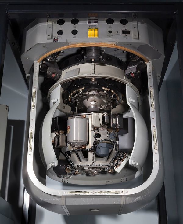
Inertial measurement unit in the human body, the human cochlea fluid-filled, people, sports, the liquid inertia can been felt the nerves in the ear, resulting in the observed acceleration of the movement. However, inertial measurement unit is very poor, close your eyes, do not touch the things around, cochlea moves alone, people can't walk a straight line.
And rotary-wing aircraft for use on low-cost MEMS IMU accuracy is worse, it measures the speed and location in a few seconds will spread to dozens of meters away, and couldn't be used to control your flight path.
In addition, the IMU will be limited by the temperature, the manufacturing process, resulting in some measure of deviation, sometimes after a sudden temperature change, for example, a stationary inertial measurement unit feel like you turned up, though it still, but the output is not zero angular velocity. This algorithm requires careful measurement deviation correction and often cannot rely on measuring the total elimination of the IMU themselves.
Magnetic compass heading is a measurement of the sensor. Compass significant role in people's lives, in an unknown environment, does not differentiate North and South may be difficult. Are heading south in the direction of the fuselage of the aircraft was north of the State in navigation terms is called the heading, or vehicle attitude in the three dimensions of a, in his navigation system is a very important State.
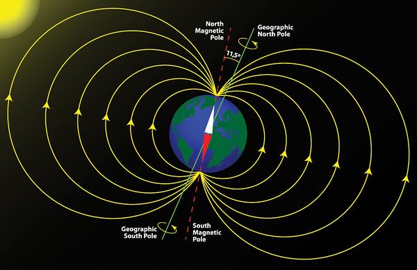
Geomagnetic compass to guide North is because the surface of the Earth in space has seen across the North-South meridians, magnetic compass can measure the geomagnetic intensity through itself, so as to deflect pointed out that the current relative to the geomagnetic lines of their own. Similarly, the theory is quite simple, but very weak geomagnetic lines, are vulnerable to disturbance. Universal brushless motors such as rotary wing aircraft, when in operation, will produce changes in the magnetic field, and after the magnetic field, magnetic compass is not found in the right direction. This characteristic of the magnetic compass is annoying, but the early days of rotary-wing aircraft developer could do nothing, because this is the only aircraft in space can be determined in the absolute equipment of course. If you do not know the course, there is no way for navigation.
The principle of the barometer is the most simple. Because the Earth's surface at higher altitudes, the air is thinner, air pressure, the lower the air pressure will give the altitude of the aircraft. However, not surprisingly is that size and weight appropriate for rotary-wing aircraft using the pressure gauge has a great defect, its measured value be affected by temperature, humidity, air flow, light, vibration and other factors influence alone very difficult to achieve a high degree of stability of the barometer measurements.
Integrated navigation technology combined with GPS, inertial measurement unit, magnetic compass and barometer of their respective advantages and disadvantages of using a lot of electronic signal processing technology, integration of a variety of sensor measurements to obtain more accurate aircraft measurements of 15 States. Mentioned above the inertial measurement unit of measurement to instability, the divergence can be inhibited by GPS: GPS position can be obtained also get three-dimensional velocity, inertial measurement unit can get the three-axis accelerometer, the integral of acceleration and speed. Obtained by magnetic compass heading on the basis of two observations can be combined by using GPS measurements to detect and inhibit the spread of inertial measurement unit. After the divergence of the inertial measurement unit is suppressed, it can more accurately measure three dimensions and three-axis accelerometer. GPS and inertial measurement unit therefore learn from each other in such cases. In addition, the barometer and GPS enhances the accuracy of height measurement with each other, the magnetic compass, GPS and inertial measurement unit with improved the heading measuring precision, they are all using the same integration, "complementary".
Integrated navigation technology in the design of compensation directly from the 1948 birth of information theory. Claude concludes Shannon's information theory proposes that concepts and how measurement information from the mathematics, information theory can be said to be one of the cornerstones of modern human civilization. Explain the nature of the information, people can be expressed as a mathematical one simple but profound principles: information may be used to estimate the status, the more information can be more accurate state estimate.
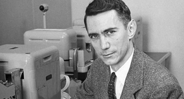
(Top pay tribute to the father of information theory, Claude Shannon)
Since then, the founder of Cybernetics, Norbert-Wiener, Rudolph-Kalman, and a host of other engineers and scientists to perfect the State estimation of linear estimation theory through information presented between the sensor "complementary filter" theory of common errors. Kalman Kalman filter design has also been achieved in the Apollo guidance computer, sign and IMU complementary measure of Apollo 15.
Information theory, linear estimation and Kalman filter to allow the integration of multiple sensors with error by mathematical equations, using sensor information of specific State, and more sensors "complementary", can get the better of the State estimate. In this way, mathematics for engineering pointed out the direction of development: build more powerful sensors complement each other, will be able to get a better estimate. Xinjiang fish adult flight control Chief Engineer once said: "the most brilliant engineers are working on sensors. "The importance of sensor technology can be seen.
As a location sensor, GPS has many of problem, GPS signal only in open of space within to to out compared good of measurement value, because GPS receiver need from heaven of satellite get signal, these signal to from space incoming atmosphere, so far of distance, signal has relative for is weak, so must requirements receiver and satellite Zhijian of line Shang no block, once has building even is trees of block, satellite sent down of signal on has noise, GPS receivers will not be given a good position and speed observation. In an indoor environment, GPS or even completely unusable. To further development of integrated navigation technology, you need to look for other sensors used in environments where GPS cannot be used.
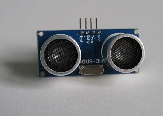
A simpler alternative to ultrasonic module for GPS sensor for measuring height is small. The module usually has one of two probes, ultrasound a probe sends another probe measurement of ECHO time, and be able to work out the cause sound waves bounce off the object distance from the probe. Taobao now for only 10 bucks you can get a more accurate measurement distance within a few metres of the ultrasonic module, is widely used in making little robot on college students. This 10 bucks sensor no barometer and MEMS inertial measurement unit much higher performance, it emits sound waves to instability, front of the detected objects are not necessarily located in the probe, sound waves are likely to be affected by the water mist, vibrations in the air, gives completely the wrong observation. Therefore, the ultrasonic module the best usage scenario is on the ground, measuring their distance and the ground.
3. visual perception system
Another alternative is the visual perception system. After 1970, with the development of digital imaging technology, as a sensor of the camera began to be studied extensively. Because people can own objects in the Visual field of the position, distance, and mechanics of the camera simulates the human eye, so the researchers to simulate human characteristics, using the camera object in a two-dimensional image reverse image of three dimensional information. This three-dimensional and two-dimensional images projected information related technical and mathematical theory developed into a separate discipline--in computer vision, also known as machine vision.
Visual perception system is currently the most popular in the world of Robotics and machine vision research in the field. The principle is to use Visual sensor system consisting of one or more cameras, using complex algorithms, by two-dimensional camera image projection in the perspective of objects and Visual sensor system for geometric center of motion information, assuming that these objects are static, so relative motion in fact represents the movement of Visual sensor itself. In theory, computer vision technology with a camera that can measure accurately the amount of 15 States, but like other sensors, the camera also has a lot of flaws, including limited size, image quality cannot be recovered, consumes a huge amount of calculation, and so on. Fortunately, our visual perception system and other sensors can be combined with each other to improve the measurement accuracy.
Astute readers must be able to think of, the visual perception system and all said before using sensor fusion for integrated navigation, GPS signal quality when using GPS navigation, no alternative GPS GPS with visual perception system, did not solve the problem. This is now the engineers and scientists are working to solve the problem, is also the Elf 4 preliminary research. Introducing Elf 4 is how to combine the visual perception system and navigation technology, we introduce two kinds of visual perception system is mature: optical flow velocity measurement module and Visual odometry.
Optical flow Velocimetry module as the name suggests, only faster. Optical flow speed is usually a module consists of a camera, an inertial measurement unit, an ultrasonic module, its main principle was developed in 1981 by the computer vision technology "optical flow tracing" algorithm.
"Flow" concept was first proposed in 1950 by psychologists and biologists, refers to an observer and observed him when there is a relative movement, these things in front of him will have a "sport mode", the human brain using this "campaign mode" can be more sensitive to sense something moving. For example, in the figure below, readers can see intuitive understanding of "flow" means.
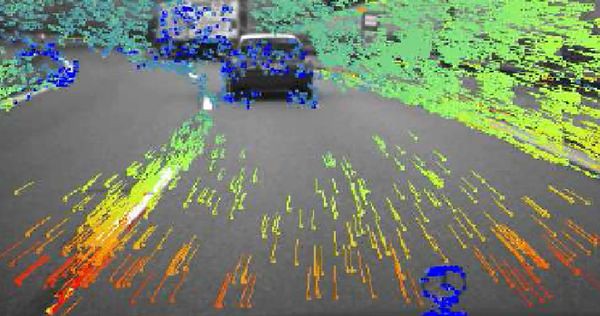
Then a computer scientist Bruce Lucas and Takeo kanade Lucas-Kanade algorithm was invented in 1981, picture taken by an algorithm to calculate the continuous stream of light on, and the optical flow can inverse the speed of relative motion. Although more than 30 years, the Lucas-Kanade algorithm has always been recognized as the best "optical flow tracing" algorithm, but it has significant limitations, it contains a number of assumptions, such as assuming the average brightness of pictures in a row of the same, such as assumptions only Planar motion of an object in a picture, and so on. In addition, flow algorithms calculate the speed of light is not scale, because the camera image in pixels, so the optical flow algorithm can only give "your speed is 10 pixels per second", but can't figure out the 10-megapixel is 1 cm or 1 m. Recovery ways of increasing plane motion of an ultrasonic module for measuring distance from the camera, so it can be converted into real pixel motion movement. Finally, if you want to let the light flow velocity module in dangling multi-rotor aircraft can also be used by inertial measurement unit to identify the image represented by the plane is essential to this need in the algorithm for two kinds of sensors are very good with.
Optical flow algorithms can only be measured on three-dimensional velocity, no direct measurement of three dimensional position. We also measured through speed module optical flow velocity integral obtained position, but as IMU score divergence, optical flow velocity integral module location will also diverge. Fortunately, it is not fanciful to spin out of control, and integrated navigation technology in addition to GPS sensor properly after the fusion, it can hover measured positions do not diverge. Therefore flow velocity measurement modules can replace the GPS only under limited conditions.
Optical flow velocity measurement module has formed a very standard solutions. Jiang Wu and Elf on the 3 mount the independent research and development of optical flow velocity measurement module, another well-known open source fly control product Pixhawk contains an optical flow Velocimetry module called PX4Flow, and all the code is open source and hardware solutions. Optical flow velocity measurement module is now widespread in many of the major manufacturers products on rotary wing aircraft.
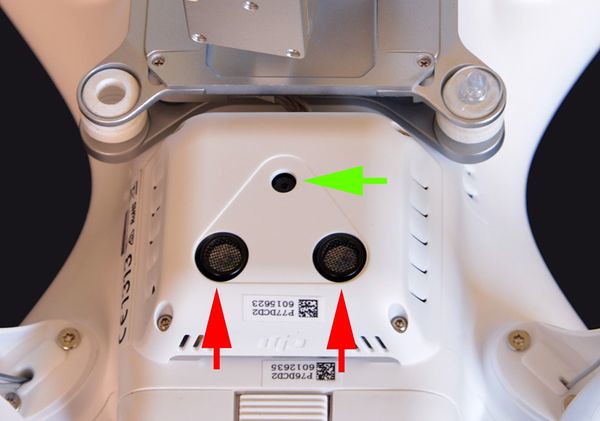
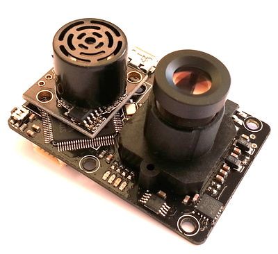
Visual odometry compared to optical flow velocity measurement module adds the ability to directly measure the position, so called "odometers". Visual odometry flow Velocimetry module more than light, and better performance.
Readers may ask, why that sound Visual odometry and optical flow velocity measurement modules involved in the number of sensors (optical flow Velocimetry module even more than an ultrasonic module), but Visual odometry ability more. Here is not the cause of sensor hardware and software algorithms. Already there are many simplifying assumptions when it comes to optical flow tracing algorithm, can only measure motion, additional sensor hardware is to some extent about convenient and simplified in order to calculate the factor to fill up again.
Visual odometry rule is more complicated, not only through the images out of Planar motion objects in the view, also out three-dimensional position of these objects and locations based on these objects do a lot of optimization, complexity multiple optical flow speed measurement module. Some Visual odometry algorithms and even contains a complete optical flow tracing algorithm, but only optical flow image as pretreatment steps of calculation.
Visual odometry is able to directly measure the position measurements are more accurate, not as divergent as the optical flow velocity measurement module. Generally excellent Visual odometry flew 100 meters only after accumulating more than 10 cm to dozens of centimeters of error, millions of on this level of measurement than missile's inertial measurement unit is bad, but considering the Visual odometry is extremely cheap, compared to its price is very high.
Visual odometry has several different levels of difficulty, the simplest is two cameras for binocular stereo vision system and inertial measurement unit, a camera is the most difficult form of monocular vision system and inertial measurement unit. If Visual odometry and optical flow Velocimetry module hardware, this Visual odometry is monocular vision system. At present, the binocular stereo vision system and inertial measurement unit to achieve their own State are well-established and comprehensive technical and monocular vision system is an active research area, do the research in the world better University United States Pennsylvania universities, Switzerland the Swiss Federal Institute of technology, United Kingdom, Oxford University, Hong Kong University of science and technology and other institutions in Europe and America.
Monocular vision and binocular vision system by contrast, difficulty of their algorithm varies widely. Algorithm key Visual odometry is the front saying "successive images out of three dimensional objects in the view." For binocular stereo vision system and structure similar to the human eye, it is easier, because an object appears in both left and right in the camera's field of vision is about vision with Parallax, Parallax can help solve the position of objects, can be realized just by simple geometry, this is a very mature technology.
But for a monocular vision system, only one camera there is no Parallax, unable to solve simple geometric relations, so the algorithm must be able to intelligently and the estimated number of objects in the local scope, and then by itself the move moving Parallax, and then make the location of maximum-likelihood estimation of multiple objects, so as to calculate the location of these objects more accurately. This process involves a number of links, most of the links are not recognized in the academic world best program, therefore there is no mature technologies.
Because the principle is relatively simple, so Visual odometry of binocular stereo vision system 30 years ago, started to be studied. In the early 1980, NASA engineers, the famous ROBOTICIST Hans Moravec has created a system of this State. Another story about Hans Moravec, I know a question "what are the quotes associated with the control, robotics and other? -YY master answer "are mentioned.
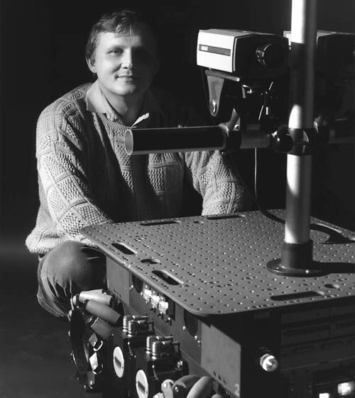
(Top pay tribute to Hans Moravec)
After years of optimization, in 2004, NASA successfully to Visual odometry and inertial measurement unit the Visual positioning system mounted on the "opportunity" and "spirit" Rover speed only 20MHz a special chip, taken to Mars, it may help the Rover through a pair of stereo cameras accurately record their pass routes. In 2007, Mars missions, a computer scientist and engineers wrote a paper in this exciting process of the computer vision of Mars (Computer Vision on Mars), this article is attracting a lot of research in computer vision researchers engaged Visual odometry, but also greatly contributed to Visual odometry applications in robotics.

No comments:
Post a Comment